Non-linear transformer, rectifier, 20ohm load, power-on transient response
Main voltage, a rectifier, a capacitor and a 20ohm load are added to
the model:
* Main voltage
V1 1 2 0V SIN 0V 312V 50HZ
* Graetz
D1 6 8 DN4001
D2 7 8 DN4001
D3 0 6 DN4001
D4 0 7 DN4001
.MODEL DN4001 D (IS=1.4N RS=0.04 N=1.7 TT=5U CJO=55P VJ=0.34 MJ=0.38
BV=75)
* Capacitor
C 8 0 1000UF
* Load
RB 8 0 20
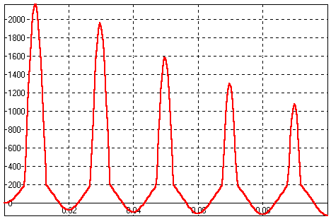 Power-on transient response, H(t) [A/m]. Time
is measured in [s].
Spikes appear, and gradually disappear again.
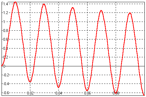 Power-on transient response, B(t) [T].
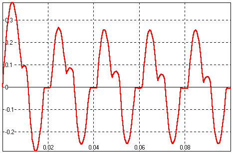 Power-on transient response, i1(t) [A].
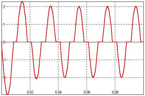 Power-on transient response, i2(t) [A].
The response shows when rectifier diodes are open
(transformer provides current).
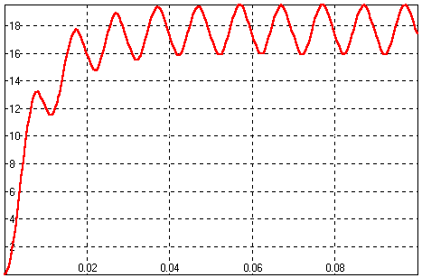 Power-on transient response, uRb(t) [V].
After power-on load voltage raises and reaches its
final value.
The ripple voltage frequency is twice the main voltage
frequency (it is doubled by the rectifier circuit).
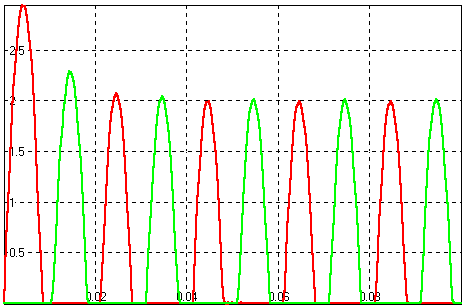 Diode currents, D1 (iD1(t) [A]) and D2
(iD2(t) [A]).
In the positive half of the sine cycle the first
pair of diodes (D1, D4) is open and in the negative half the second pair
(D2, D3).
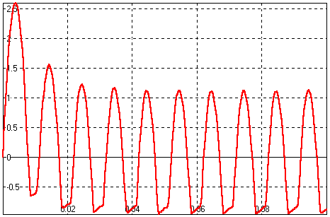 Capacitor current iC(t) [A].
|
