Open circuit secondary coil
The 'European' main voltage is connected to the primary coil:
V1 1 2 0V SIN 0V 312V 50HZ
Power-on transient:
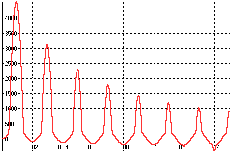 Power-on transient response, H(t) [A/m]. Time is
measured in [s].
Immediately after the power-on the transformed core
reaches saturation. The saturation is at first reached only once per sine
cycle.
The spikes that appear become significantly lower
after 10 sine cycles.
The remaining spikes (up and down) are caused by
the open circuit secondary coil which can't balance out the primary coil
current.
Large values of H cause large forces in the core.
The core twitches when the power is switched on.
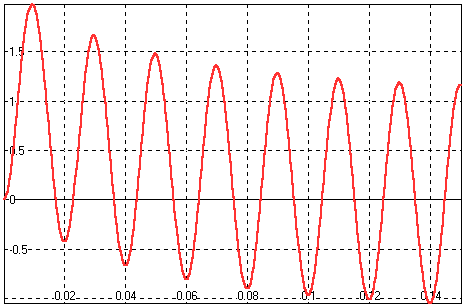 Power-on transient response, B(t) [T].
The response is a superposition of a sine and a falling
exponential function.
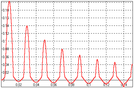 Power-on transient response, i1(t) [A].
The wave form is the same as in H(t) (see the equation
on previous page H(i1, i2=0))
Steady state:
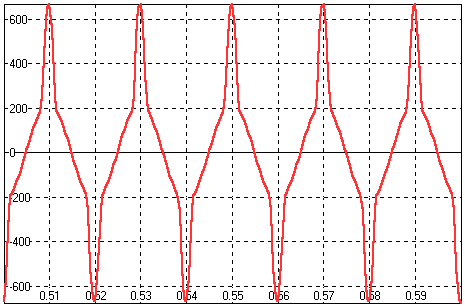 Steady state, H(t) [A/m].
Two spikes appear in one sine cycle when the core
reaches saturation.
Spikes appear because there is no secondary coil
current to balance out the primary current.
The H(t) is dictated by B(t) which must be sufficient
for dB/dt to provide primary coil induced voltage keeping balance with
the main voltage
(assuming the voltage on RTR1 is negligible).
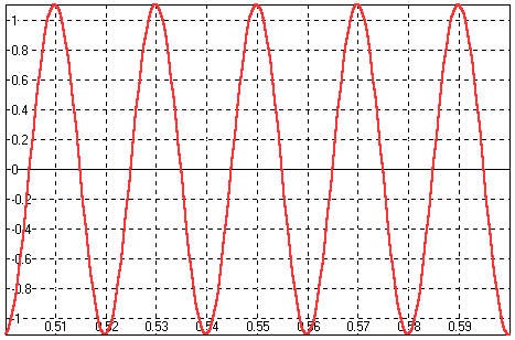 Steady state B(t) [T].
Obviously this is a sine since RTR1 voltage (caused
by the primary coil current i1) is insignificantly low.
The current flowing in the primary coil is just the
magnetization current.
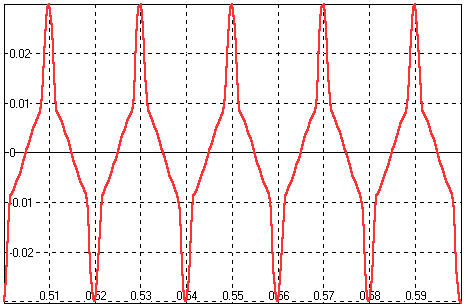 Steady state i1(t) [A].
This is the magnetization current.
|

