20ohm load on the secondary coil
Main voltage and load resistance are added to the transformer model:
V1 1 2 0V SIN 0V 312V 50HZ
RB 6 7 20ohm
Power-on transient:
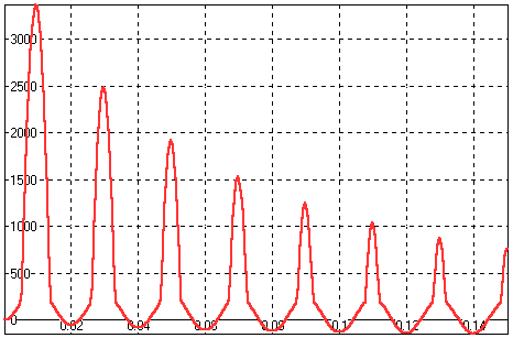 Power-on transient response, H(t) [A/m]. Time is
measured in [s].
Same as the open circuit secondary coil. Spikes appear
after power-up.
The difference is that they disappear completely
when steady state is reached.
The spikes are somewhat lower (about 30%) since the
secondary coil current is trying to keep balance with the primary current.
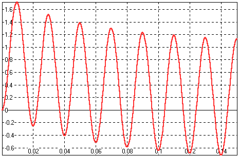 Power-on transient response: B(t) [T].
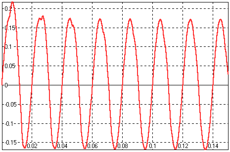 Power-on transient response, i1(t) [A].
Steady state:
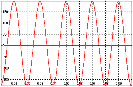 Steady state, H(t) [A/m].
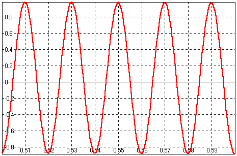 Steady state, B(t) [T].
Nothing much happening here, the same as in the previous
example.
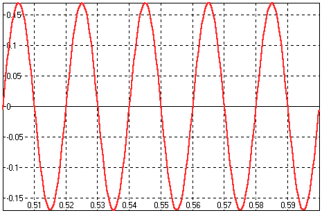 Steady state, i1(t) [A].
The current is larger since now the secondary coil
must supply the load with current.
Steady state responses are all harmonic, the transformer operates in
the linear part of the B(H) characteristic. The reason is the secondary
coil current which keeps balance with the primary coil current preventing
the core from reaching saturation.
If load resistance is increased to a point where secondary coil current
can't keep up with the primary coil current, spikes in the H(t) response
reappear. The nominal load value is the load where the transformer operates
just below saturation. In the latter case it is 20ohm. Try experimenting
with larger values.
|
