updated 2000.03.30
Author Janez Puhan
Active Low-pass RC Filter
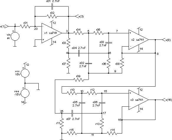
The circuitLet us consider the optimisation of the active low-pass RC filter. We will use the constrained simplex optimisation method. The circuit topology is shown in the figure below.

The filter is built around three standard operational amplifiers UA741. All capacitances are set to the same value of 2.7nF. The values of all resistances are left undetermined and are subject to optimisation process.
Here is the netlist of the circuit (part of active_low-pass_rc_filter.cir file):
*** active low-pass rc filter ***

vcc 12 0 dc 15V
vee 14 0 dc -15V
vin 1 0 dc 0 ac 1V 0

r01 20 1 50k
r02 20 3 500k
r03 3 4 2.5k
r04 3 5 250k
r05 5 7 500k
r06 6 9 50k
r07 4 0 50
r08 8 9 500
r09 9 25 500
r10 10 8 250k
r11 25 0 500
r12 10 15 250k
r13 17 11 50k
r14 16 11 50
r15 11 0 2.5k

c01 20 3 2.7nF
c02 5 9 2.7nF
c03 7 6 2.7nF
c04 4 6 2.7nF
c05 10 11 2.7nF
c06 15 17 2.7nF
c07 25 17 2.7nF

x1 0 20 3 12 14 ua741
x2 7 8 8 12 14 ua741
x3 15 16 16 12 14 ua741

.subckt ua741 11 5 4 6 2
vof 5 10 dc 1mV

ibn 5 0 dc 100nA
ibp 11 0 dc 80nA

r1 7 1 5k
r2 8 7 50k
rid 10 11 200k
rin 5 0 10meg
rip 0 11 10meg
rl1 3 4 1k
ro 3 0 75
rp 2 6 10k
rxx 0 2 10meg

c1 7 0 13pF
c2 8 3 2.7pF
cin 5 0 1.4pF
cip 11 0 1.4pF
cl1 4 0 3pF

l1 3 4 30uH

ea 1 0 10 11 1

ga 3 0 8 0 2700S
.ends

.end

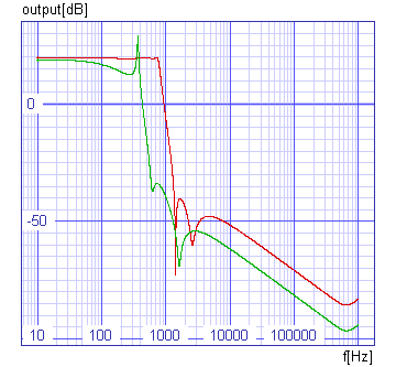
The cost function is defined by the boundaries in the figure above. We tolerate a 0.5dB ripple, further we demand at least 60dB damping and a don't care band is from 750Hz to 1.35kHz. At the same time we would like to have at least 20dB gain at low frequencies. So we are looking for the resistances r1 to r15, which will give the most appropriate frequency response. We set the explicit constraints of the all resistances to:
10kW < r1 < 100kW
100kW < r2 < 1MW
500W < r3 < 5kW
50kW < r4 < 500kW
100kW < r5 < 1megW
10kW < r6 < 100kW
10W < r7 < 100W
100W < r8 < 1kW
100W < r9 < 1kW
50kW < r10 < 500kW
100W < r11 < 1kW
50kW < r12 < 500kW
10kW < r13 < 100kW
10W < r14 < 100W
500W < r15 < 5kW
Now we have to mathematically define the cost function. Its value has to increase with ripple greater than 0.5dB, damping less than 60dB and gain less than 20dB.


There are no implicit constraints, so all we have to do is to run the optimisation process and wait for the results. The optimisation is performed by optimize command. It stops after 3433 iterations and the value of the cost function equals to 1.26. That means that not all the requests determined by the cost function were fulfiled. Our optimised filter has 0.59dB ripple, 60dB damping and 19.6dB gain. The figure below shows the ac responses of the initial and optimised circuit.
