updated 2000.03.30
Author Janez Puhan
Bistable Multivibrators
The circuit
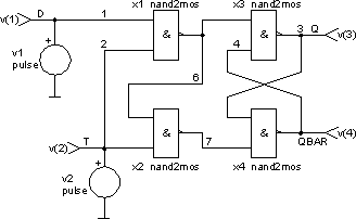
Bistable multivibrators have the property being able to maintain one of two possible states. Though similar to Schmitt triggers, they differ in that the changing of states is evoked by subsequent and equally shaped trigger pulses. These so-called flip-flops are the basic memory blocks for binary signals. The following is a simple latch flip-flop. It consists of four NAND gates. When the clock input is set to T = 1, the binary variable, D, at the delay input is shifted to the output, Q. If clock input is set to T = 0, the output, Q, is isolated from D. The latch may be realised with OR gates as well. The described functionality will then arise when clock signal is inverted.

The input file
bistable multivibrator

.control
set abstol = 1e-10
tran 0.1s 10s
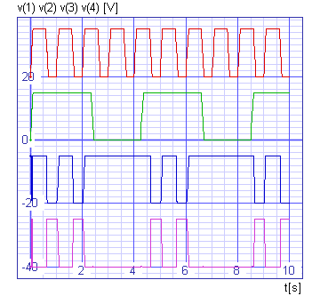
plot v(1)+20 v(2) v(3)-20 v(4)-40 xlabel t[s] ylabel 'v(1) v(2) v(3) v(4) [V]'
  + title 'TRAN analysis'
.endc

v1 1 0 dc 0 pulse 0 15V 0 0 0 0.5s 1s
v2 2 0 dc 0 pulse 0 15V 0 0 0 2.25s 4.25s

x1 2 1 6 nand2mos
x2 2 6 7 nand2mos
x3 4 6 3 nand2mos
x4 7 3 4 nand2mos

.subckt nand2mos 1 2 3
v1 4 0 dc 15V

c1 1 0 5pF
c2 2 0 5pF

m1 3 1 4 4 noname1
m2 3 2 4 4 noname1
m3 5 1 0 0 noname2
m4 3 2 5 5 noname2

.model noname1 pmos
.model noname2 nmos
.ends

.end
The results
