updated 2000.12.08
Author Janez Puhan
Astable Multivibrators
The astable or free running multivibrator has no stable operating point. It is used for generating a steady stream of stimulus waveforms. Amplifiers with positive feedback are necessary to excite and maintain the continuous oscillations. In contrast to the oscillator described in Sine Wave Oscillator With CMOS Inverter case, which has an LC resonant circuit, capacitors and resistors are inserted in the feedback loop to define the frequency of oscillation.
Two practical circuits are shown. The first one contains bipolar transistors in a symmetrical arrangement, While the second one contains CMOS inverters.
The circuit 1
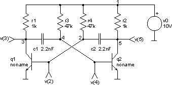
The input file 1
astable transistor multivibrator
.control
tran 2.5us 500us uic
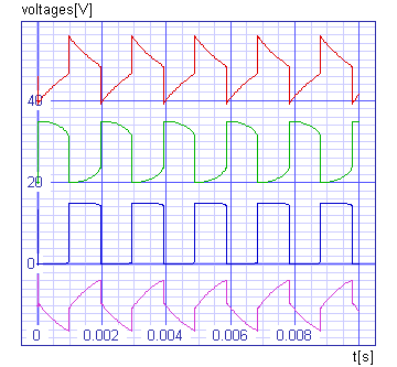
plot v(2)+12 v(3)+15 v(4) v(5)-20 xlabel t[s] ylabel voltages[V]
+ title 'TRAN analysis of transistor multibibrator'
.endc
v0 1 0 dc 10V
r1 1 3 1k
r2 1 5 1k
r3 1 4 47k
r4 1 2 47k
c1 3 4 2.2nF ic=10V
c2 2 5 2.2nF
q1 3 2 0 noname
q2 5 4 0 noname
.model noname npn cjc=4pF
.end
The results 1
The circuit 2
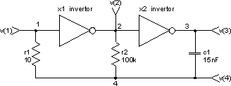
The input file 2
astable cmos multivibrator
.control
tran 0.05ms 10ms uic
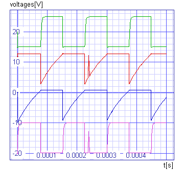
plot v(1)+40 v(2)+20 v(3) v(3,4)-10 xlabel t[s] ylabel voltages[V]
+ title 'TRAN analysis of cmos multivibrator'
.endc
r1 1 4 10
r2 2 4 100k
c1 3 4 15nF ic=7.5V
x1 1 2 invertor
x2 2 3 invertor
.subckt invertor 1 2
v1 3 0 dc 15V
d1 1 3 diode
d2 0 1 diode
m1 2 1 3 3 p4007 w=120u l=6u
m2 2 1 0 0 n4007 w=120u l=6u
.model diode d cjo=10pF
.model p4007 pmos
.model n4007 nmos
.ends
.end
The results 2