updated 2000.12.08
Author Janez Puhan
Schmitt Trigger
The circuit
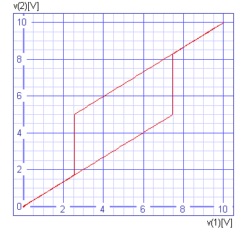
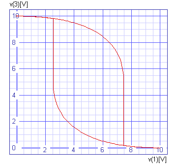
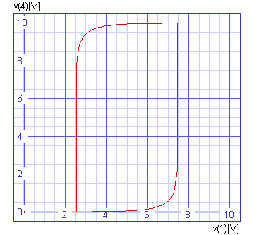
In this example, four CMOS inverters are cascaded to assure enough gain. Hysteresis is defined to be 5V by resistors r1 and r2.

The input file
schmitt trigger

.control
tran 0.05s 10s
plot v(2) vs v(1) xlabel v(1)[V] ylabel v(2)[V] title 'TRAN analysis'
plot v(3) vs v(1) xlabel v(1)[V] ylabel v(3)[V] title 'TRAN analysis'
plot v(4) vs v(1) xlabel v(1)[V] ylabel v(4)[V] title 'TRAN analysis'
plot v(6) vs v(1) xlabel v(1)[V] ylabel output[V] title 'TRAN analysis'
.endc

v1 1 0 dc 0 pwl 0 0 5s 10V 10s 0

r1 2 1 10k
r2 2 6 20k

x1 2 3 inverter
x2 3 4 inverter
x3 4 5 inverter
x4 5 6 inverter

.subckt inverter 1 2
v0 3 0 dc 10V

c1 1 0 10pF

m1 2 1 3 3 p4007 w=120u l=6u
m2 2 1 0 0 n4007 w=120u l=6u

.model p4007 pmos
.model n4007 nmos
.ends

.end
The results


