Author Ananda Murthy R. S.
by A.E.Fitzgerald, David E.Higginbotham, and Arvin Grabel,
ISBN 0-07-021152-3,
Fourth Edition, 1975,
McGraw-Hill Kogakusha Ltd.
This example is meant for novice users of SPICE OPUS to help them become familiar with steady-state analysis of a network excited by DC excitation.
PROBLEM:
In the network shown in Figure-1 below determine the voltage Va and current delivered by the controlled source. Also prove Kirchhoff's Voltage Law and Kirchhoff's Current Law.

EXPLANATION:
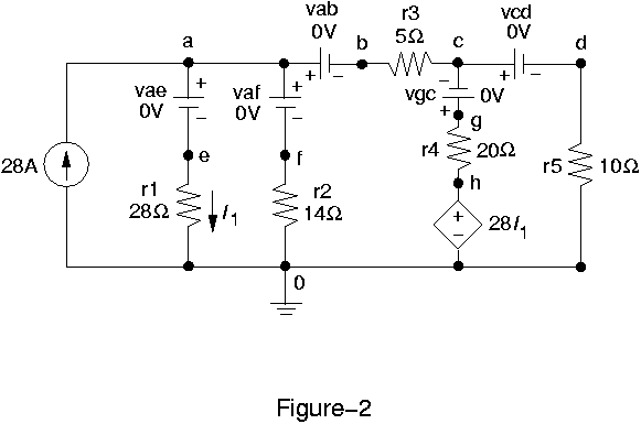
Figure-2 shows the circuit simulated using SPICE OPUS. Observe how dummy voltage source is introduced in each branch to measure branch current. SPICE OPUS always calculates current entering the positive terminal of a voltage source. Dummy voltage source polarity is based on this.

The first line in the circuit file is the title of the circuit. Here the title is KIRCHHOFF'S LAWS. It is good practice to use only small letters in the circuit file. At SPICE OPUS prompt you can type 'help' to get help. Lines describing component connections must begin from the first column. Datum node must be always indicated with number 0. Other nodes may be indicated with alphabets or numbers.
Comment line in a circuit file should always start with a * in the first column.
This is how a dc current source is represented:
i??????? fromnode tonode dc value.
Here ??????? can be any alphabet or number.
This is how a CCVS is represented:
h??????? n+ n- vnam value
Here 'vnam' is the name of the voltage source through which the controlling current flows and 'value' is the transresistance in ohms.
This is how a dc voltage source is represented:
v??????? n+ n- dc value
All control statements should be enclosed by .control and .endc statements. Control statements indicate what type of analysis is performed on the circuit and what/how results are output.
The op command calculates dc voltages of all nodes and dc through all voltage sources assuming inductances (if any) to be short circuits and capacitors (if any) to be open circuits.
Observe how messages can be echoed in the output using echo command.
Observe how expressions can be included in print statements.
i(vab) means current through the voltage source vab.
v(a,c) means v(a)-v(c)
All circuit files must end with .end statement. Type a blank like after .end to avoid premature EOF warning.
Create the circuit file given below using a text editor without any formatting and save it as a *.cir file. Then start SPICE OPUS. At SPICE OPUS prompt type 'source filename.cir' to run simulation and get results. Your results should tally with what is given below.
CIRCUIT FILE:
KIRCHHOFF'S LAWS

* Sources
i 0 a 28
h h 0 vae 28

* These dummy voltage sources work as ammeters:
vae a e dc 0
vaf a f dc 0
vab a b dc 0
vcd c d dc 0
vgc g c dc 0

* Resistors
r1  e 0 28
r2  f 0 14
r3  b c 5
r4  g h 20
r5  d 0 10

.control
op
echo Answers are:
print v(a) i(vgc)
* This gives a blank line
echo
echo These are KVL equations:
echo
print v(a)-v(a,c)+v(h,g)-v(h)
print v(h)-v(h,g)-v(d)
echo
echo These are KCL equations:
echo
print 28-i(vae)-i(vaf)-i(vab)
print i(vab)+i(vgc)-i(vcd)
echo
echo Observe the values printed are almost zero.
echo
echo
.endc

.end
RESULTS:
Circuit: KIRCHHOFF'S LAWS

Answers are:
v(a) = 1.704348e+02
i(vgc) = 2.434783e+00

These are KVL equations:

v(a)-v(a,c)+v(h,g)-v(h) = 0.000000e+00
v(h)-v(h,g)-v(d) = 0.000000e+00

These are KCL equations:

28-i(vae)-i(vaf)-i(vab) = 3.552714e-15
i(vab)+i(vgc)-i(vcd) = 3.552714e-15

Observe the values printed are almost zero.