updated 2000.03.30
Author Janez Puhan
AC to DC Power Supply
The circuit
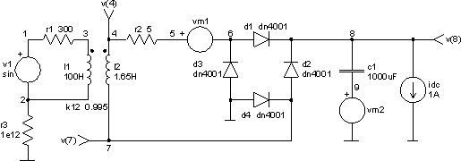
The following circuit is widely known unregulated power supply. It is used in nearly all stationary electronic equipment. Four rectifiers forming a full wave bridge generate a pulsating dc current which is smoothed by a more or less voluminous capacitor. If the instantaneous ac voltage is below the dc voltage of the capacitor, the rectifiers become nonconducting, if the voltage is higher, they will conduct. The width of the dc pulses is expressed by the rectifier conducting angle, which can be related to the total ac period, T = 20ms ~ 360°.
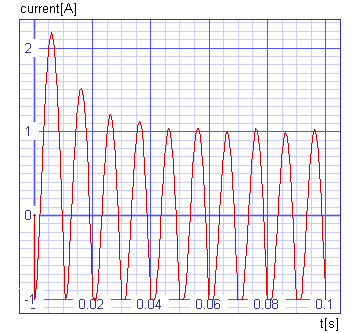
With the dc load removed from output terminals, the capacitor will be charged up to the rectifier input peak voltage and the conducting angle will be equal zero. As the output current increases, the angle increases as well. Conversion efficiency will therefore decrease, as it is dependent on the cosine of the conduction angle only. The full load efficiency should not drop below 75%. Cross sections of the windings and rectifiers, therefore, have to be chosen carefully so that the conduction angle remains below 2 * Q = 5ms ~ 90°.

The input file
ac to dc power supply

.control
tran 0.5ms 100ms uic
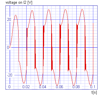
plot v(4,7) xlabel t[s] ylabel 'voltage on l2 [V]' title 'TRAN analysis'
plot v(8) xlabel t[s] ylabel output[V] title 'TRAN analysis'
plot i(vm1) xlabel t[s] ylabel current[A] title 'TRAN analysis'
plot i(vm2) xlabel t[s] ylabel current[A] title 'TRAN analysis'
.endc

v1 1 2 dc 0 sin 0 312V 50Hz
vm1 5 6 dc 0
vm2 9 0 dc 0

idc 8 0 1A

r1 1 3 300
r2 4 5 5
r3 2 0 1e12

l1 3 2 100H
l2 4 7 1.65H

k12 l1 l2 .995

c1 8 9 1000uF ic=0

d1 6 8 dn4001
d2 7 8 dn4001
d3 0 6 dn4001
d4 0 7 dn4001

.model dn4001 d (is=1.4n rs=0.04 n=1.7 tt=5u cjo=55p vj=0.2 mj=0.38 bv=75)

.end
The results


