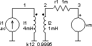
Current Transformer
The circuit
Transformers may be simulated using coupled inductors if only the linear part of the magnetisation characteristic is utilised. The primary and secondary inductances are labeled normally with the inductor node numbers determining polarity. Note, that the current always flows into the plus terminal of an element. For the inductor statement, lname node1 node2 value, the first node number, node1, is the plus node ad therefore, where positive current will flow. Coupling between the inductor windings must be defined by a coupling coefficient statement which uses key letter k. The coupling coefficient, which is entered last on the k statement, is a measure of linkage between the magnetic fluxes of each inductor. Due to the inevitable leakage, the value of the coupling coefficient can never be one and value of k greater or equal to one will be rejected. For M and EI profiles, a leakage coefficient of s = 1% … 5% should be specified. Toroidal transformers obtain a s = 0.1% because the windings and core form an annular loop, which offers the lowest possible resistance to the magnetic field. The leakage coefficient may easily be verified by measuring the ratio of input inductances, once with shorted output and once with opened output.
The input file
Current Transformer

* k = Coupling Coefficient
* 0 < k <= 1

.control
set units = degrees
ac dec 50 10mHz 10Hz
plot 50*mag(i(vm)) ph(i(vm)) xlabel f[Hz]
  + ylabel 'secondary current magnitude [A] / phase[degree]' title 'AC analysis'
.endc

i1 0 1 dc 0 ac 1

vm 3 0 dc 0

r1 2 3 1m

l1 1 0 4mH
l2 2 0 1mH

k12 l1 l2 0.9995

.end
The results

|
