updated 2000.03.30
Author Janez Puhan
Band-Pass Filter
A bandpass filter attenuates lower and higher frequencies while medium frequencies are passed through. With a narrow pass band, a resonant peak may occur, depending on the circuit's Q, which is the ratio of the center frequency to the bandwidth of the filter. Circuit Q and the damping coefficient are related by the equation Q = 1 / (2 d).
In ratio receivers, resonant LC circuits are used to select a single radio station from a bulk of others at the antenna output. In the past. circuit Q, and therefore, selectivity, could be adjusted by applying positive feedback.
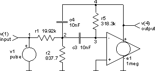
In present times, high Q bandpass filters are built with operational amplifiers having multiple feedback networks. This applies especially to low frequency circuits, where bulky inductors and capacitors would be an impending and costly factor.
The circuit

The input file (band-pass_filter.cir)
band-pass filter

* Q = fo / BW = 1 / (2 d)
* BW    Bandwidth
* fo    Center Frequency
* d     Damping Coefficient
* A     Gain
* c4 = c3
* r1 = 1 / (4 pi fo c3 d A)
* r2 = r1 / (1 / (2 A d^2) - 1)
* r5 = 1 / (2 pi fo c3 d)

.control
set units = degrees
ac dec 50 100Hz 100kHz
* phase should be continuous
let phase = vp(4) - 360 * (vp(4) gt 0)
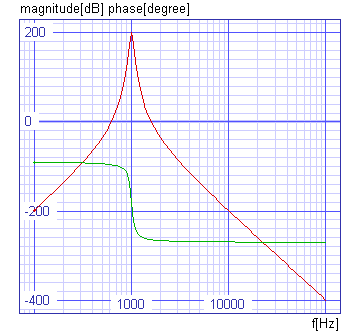
plot 10*vdb(4) phase xlabel f[Hz] ylabel 'magnitude[dB] phase[degree]'
  + title 'AC analysis'
unlet phase
tran .05ms 10ms
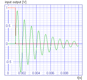
plot v(1)+1 v(4) xlabel t[s] ylabel 'input output [V]' title 'TRAN analysis'
.endc

v1 1 0 dc 0 ac 1 pulse 0 -1V 1ms

e1 4 0 0 3 1meg

r1 1 2 15.92k
r2 2 0 837.7
r5 3 4 318.3k

c3 2 3 10nF
c4 2 4 10nF

.end
The results

