updated 2000.03.30
Author Janez Puhan
High-Pass Filter
The circuit
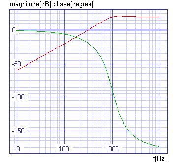
Additional building blocks for automatic control systems are represented by first and second order lead networks. In contrast to lag networks, the change in the magnitude curve now occurs below cutoff frequency. Generally, there is a definite relationship between the slope of the magnitude curve and the maximum or the phase shift curve. +6dB/octave corresponds to +90 degrees, -6dB/octave corresponds to -90 degrees. With second order systems, +12dB/octave corresponds to +180 degrees and -12dB/octave corresponds to -180 degrees. Transfer functions of higher order may be achieved by cascading the basic building blocks. Adjustment of individual damping coefficients and cutoff frequencies depends on the required overall response. These may be derived from Bessel, Butterworth, or Chebyshev polynomials. A second order lead network may be realised with circuit below.

The input file (high-pass_filter.cir)
high-pass filter

* fo = 1kHz   Cutoff Frequency
* A = 10      Gain
* d = 0.5     Damping Coefficient
* c1 = c3
* c4 = c1 / A
* r2 = d / (2 pi fo c1 (1 + 1 / (2 A)))
* r5 = (A + 1 / 2) / (2 pi fo c1 d)

.control
set units = degrees
ac dec 50 10Hz 10kHz
plot vdb(4) vp(4) xlabel f[Hz] ylabel 'magnitude[dB] phase[degree]'
  + title 'AC analysis'
tran 0.05ms 5ms
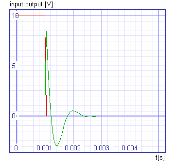
plot 10*v(1)+10 v(4) xlabel t[s] ylabel 'input output [V]' title 'TRAN analysis'
.endc

v0 1 0 dc 0 pulse 0 -1 1ms ac 1

r2 2 0 7.579k
r5 3 4 334.2k

c1 1 2 10nF
c3 2 3 10nF
c4 2 4 1nF

e1 4 0 0 3 1meg

.end
The results

