updated 2000.03.30
Author Janez Puhan
Low-Pass Filter with Transistor
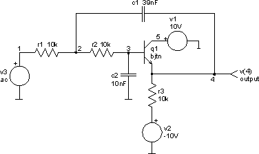
The circuit
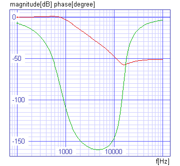
The ideal active device (voltage controlled voltage source) from previous example is replaced with a transistor acting as a unity gain emitter follower in this example. Simulation shows that the frequency response agrees with the graph from previous example at up to ten times the cutoff frequency. At higher frequencies, attenuation is limited to a value depending on the output impedance of the bipolar transistor.
The input file (low-pass_filter_with_transistor.cir)
low-pass filter with transistor

* f0 = 1 / (2 pi (r1 r2 c1 c2)^(1 / 2))   Cutoff Frequency
* d = (1 + r1 / r2) (r1 c2 / (4 r2 c1))   Damping Coefficient

.control
set units = degrees
ac dec 50 100Hz 100kHz
plot vdb(4) vp(4) xlabel f[Hz] ylabel 'magnitude[dB] phase[degree]'
  + title 'AC analysis'
.endc

v1 5 0 dc 10V
v2 6 0 dc -10V
v3 1 0 dc 0 ac 1

r1 1 2 10k
r2 2 3 10k
r3 4 6 10k

c1 2 4 39nF
c2 3 0 10nF

q1 5 3 4 bjtn

.model bjtn npn

.end
The results