updated 2000.03.30
Author Janez Puhan
Low-Pass Filter
The circuit
The RC combination is referred to as a simple lag network and is a basic building block used in automatic control systems. Low frequency inputs are transferred to the output without attenuation or lag. Above the cutoff frequency however, the frequency response decreases with a slope of 6dB/octave. Phase shift develops gradually from zero to -90 degrees.
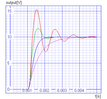
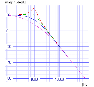
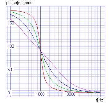
In this example another building block is shown. It has a more complex transfer function and is called a second order lag. The phase shifts from zero to -180 degrees and the magnitude attenuates at 12dB/octave at higher frequencies. A particularly interesting response occurs in the vicinity of the cutoff frequency. There may be a more or less resonant peak in the amplitude response, depending on the damping ratio, d. For , d = 0.2 this amounts to 8dB and for d = 1 it will be -6dB.
A physical realisation of the transfer function may be implemented using the circuit below, which can then be analysed by Spice Opus. The simulation results agree with the theoretical response. The step response has also been simulated and is shown in the graphs below. A slight peak occurs in the transient response due to the damping coefficient, d = 0.5.
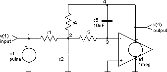
The input file (low-pass_filter.cir)
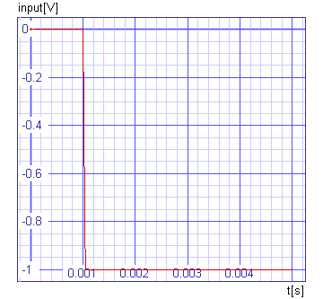
low-pass filter

* fo = 1kHz            Cutoff Frequency
* A = 10               Gain
* d = 0.2, 0.5, 1, 2   Damping Coefficient
* c2 = (A + 1) c5 / d^2
* r1 = d / (2 pi fo A c5)
* r3 = A r1 / (A + 1)
* r4 = A r1

.control
let gain = 10
let cutoff = 1k
let c5 = 10n
set units = degrees
foreach parameter 0.2 0.5 1 2
  let d = $parameter
  alter c2 capacitance = (gain + 1) * c5 / d^2
  let r1 = d / (2 * pi * cutoff * gain * c5)
  unlet d
  alter r1 resistance = r1
  alter r3 resistance = gain * r1 / (gain + 1)
  alter r4 resistance = gain * r1
  unlet r1
  ac dec 50 100Hz 100kHz
  tran 0.05ms 5ms
end
unlet gain
unlet cutoff
unlet c5
unset parameter
plot v(1) xlabel t[s] ylabel input[V] title 'TRAN analysis'
plot tran1.v(4) tran2.v(4) tran3.v(4) tran4.v(4) xlabel t[s] ylabel output[V]
  + title 'TRAN analysis'
setplot ac1
plot db(ac1.v(4)) db(ac2.v(4)) db(ac3.v(4)) db(ac4.v(4)) xlabel f[Hz]
  + ylabel magnitude[dB] title 'AC analyses'
plot ph(ac1.v(4)) ph(ac2.v(4)) ph(ac3.v(4)) ph(ac4.v(4)) xlabel f[Hz]
  + ylabel phase[degrees] title 'AC analyses'
unset units
destroy all
.endc

v1 1 0 dc 0 ac 1 pulse 0 -1 1ms

r1 1 2 0
r3 2 3 0
r4 2 4 0

c2 2 0 0
c5 3 4 10nF

e1 4 0 0 3 1meg

.end
The results