updated 2000.03.30
Author Janez Puhan
Amplifier With CMOS Inverters
The circuit
In this example, the linearizing property of negative feedback is studied. The amplifier uses complementary MOS field effect transistors similar to the well known 4007 device in the CMOS logic family. When using logic gates for analog applications, the linear part of the transfer characteristic is utilized. This is accomplished by the feedback resistor , r2, which sets the operating point to the half the supply voltage. The characteristic of a single gate isn't quite linear, therefore, three stages have to be cascaded in order to get good overall linearity.
All of the gates are identical, so a single subcircuit, which will be called three times, may be used. Use of subcircuits results in a simplification of the SPICE netlist because MOSFETs m1 and m2, supply voltage v0, and the gate capacitance c1 only have to be defined once.

The input file (amplifier_with_cmos_inverters.cir)
amplifier with cmos inverters

.control
dc v1 0 10V 5mV
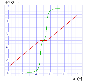
plot v(2) v(4) xlabel v(1)[V] ylabel 'v(2) v(4) [V]' title 'DC analysis'
plot v(3) v(5) xlabel v(1)[V] ylabel 'v(3) v(5) [V]' title 'DC analysis'
.endc

v1 1 0 dc 0

x1 2 3 inverter
x2 3 4 inverter
x3 4 5 inverter

r1 1 2 10k
r2 2 5 100k

.subckt inverter 1 2
v0 3 0 dc 10V
c1 1 0 10pF
m1 2 1 3 3 p4007 w=120u l=6u
m2 2 1 0 0 n4007 w=120u l=6u
.model p4007 pmos
.model n4007 nmos
.ends

.end
The results

